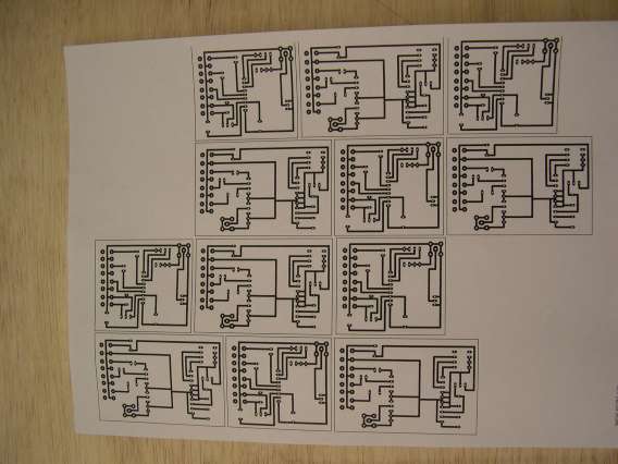
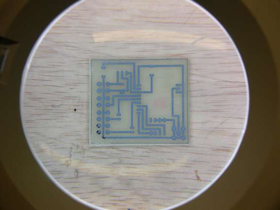
The circuit layouts and components are shown on the schematics that are supplied with the Tx and Rx modules. They are downloadable from the Active Robots site. From these, it is possible to design the tracks for the PCB.
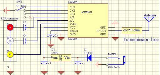
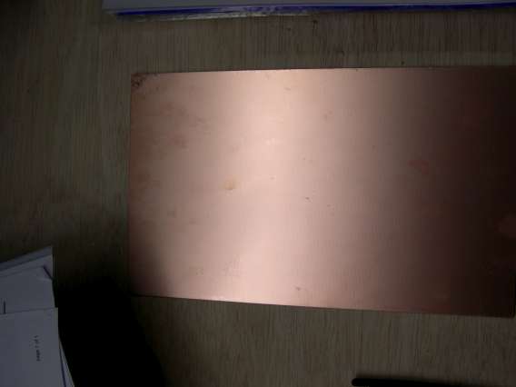
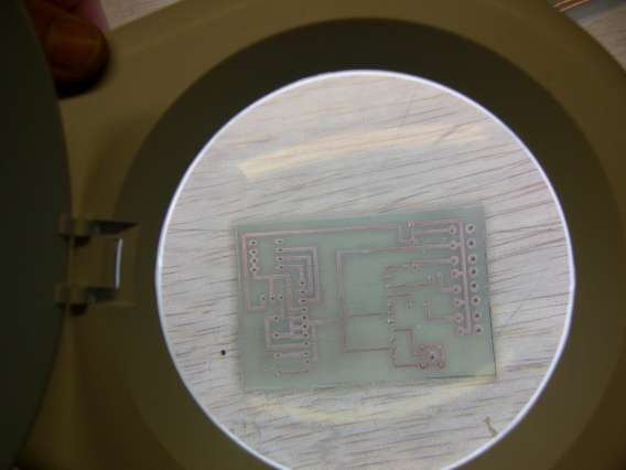
They are made from PCB Wizard circuit design software, then laser printed onto special 'Print and Peel' transfer paper. The image on the transfer paper is then ironed onto the copper board. The copper board is then etched to remove all copper except the circuit which is under the ironed on transfer.
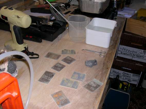
The ironed on transfer is then cleaned away using fine wire wool, leaving the shiny copper circuit

It is important to get the holes in the PCB vertical, otherwise it can be a real pain to get the modules installed................
The centre hole for the SMA connector for the antenna needs a slightly bigger hole.
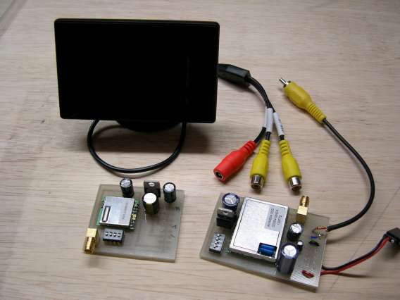
The strip boards in the background are the first tests of the circuit before making the PCB
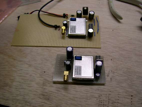
With the L7805 voltage regulator shown on these boards, there needs to be at least 2 volts more coming into the regulator in order for there to be 5v coming out; I did not realise this for a while, and that can get quite frustrating as well.
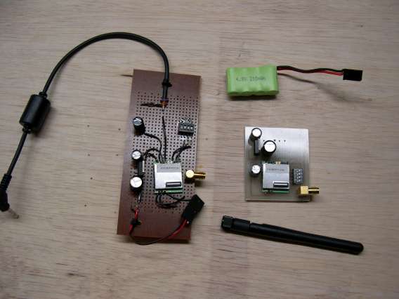
The screen is from Ebay, and runs from a nominal 12volts.
Update as at September 2010: Using 2904-05 voltage regulator gives the same power out, but with much less voltage drop, and its the same physical size, so was a straight replacement! Just need to reduce the size of the board as there is a lot of spare space, then get it into a box so it looks tidy.